In medium and low voltage switchgear, overheating is often perceived as a result of undersized busbars or overloaded systems. However, real-world experience shows that most general busbar arrangements, when designed per industry standards, do not encounter temperature rise issues. Instead, thermal hotspots—specific areas with concentrated heat generation and poor dissipation—are the true culprits.
Where Are the Real Problems?
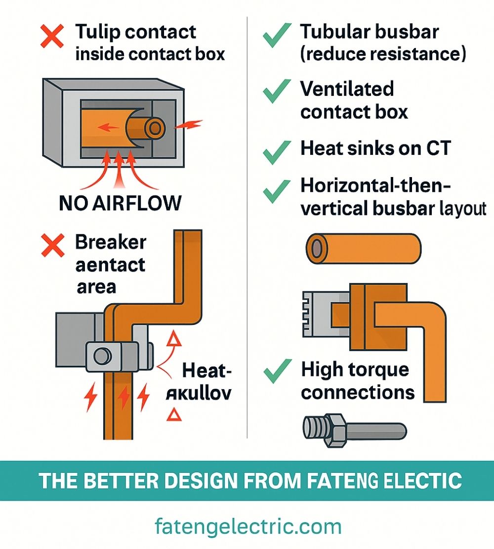
One of the most common sources of overheating lies in tulip contacts (moving contact arms) of withdrawable circuit breakers, especially in metal-clad switchgear (e.g., center-mounted designs).
-
The tulip contact is inserted into a contact box and connects with the static contact.
-
Due to the large dynamic contact resistance and the enclosed space, heat builds up rapidly.
-
There is no air circulation channel in the contact box, limiting both radiation and convection cooling.
-
This localized heat cannot escape efficiently, leading to temperature rise beyond acceptable limits.
Similar problems exist in low voltage switchgear:
-
The contacts of draw-out type breakers generate significant heat.
-
When busbars are vertically connected in close proximity to the breakers, thermal concentration occurs.
-
This combination results in high local temperatures and potential thermal failure if not properly managed.
Introducing TNT: Thermal Network Technology
Thermal Network Technology (TNT) is an analytical approach that models each node in the switchgear circuit, evaluating both heat generation and dissipation. TNT allows engineers to:
-
Identify precisely which components exceed thermal thresholds
-
Take targeted measures to reduce heat generation and enhance heat dissipation
TNT-Based Optimization Strategies:
-
Reduce Contact Resistance
-
Increase the cross-sectional area of static contacts
-
Use thicker contact arms and copper bars to lower loop resistance
-
-
Enhance Heat Dissipation
-
Use ventilated contact boxes to create airflow channels
-
Apply heat sinks at critical outlets or install them on CTs (current transformers)
-
Paint partitions in busbar compartments black to improve radiation efficiency
-
-
Leverage Temperature Gradient for Cooling
-
Lowering copper bar temperature near the CT enhances the thermal gradient between the CT and the static contact, improving conduction and overall cooling effect
-
-
Improve Circuit Breaker Heat Flow
-
Analyze air circulation around frame circuit breakers
-
Leave ventilation openings in mounting plates and compartments
-
Design a vertical air path to allow natural upward airflow
-
-
Avoid Localized Heat Accumulation
-
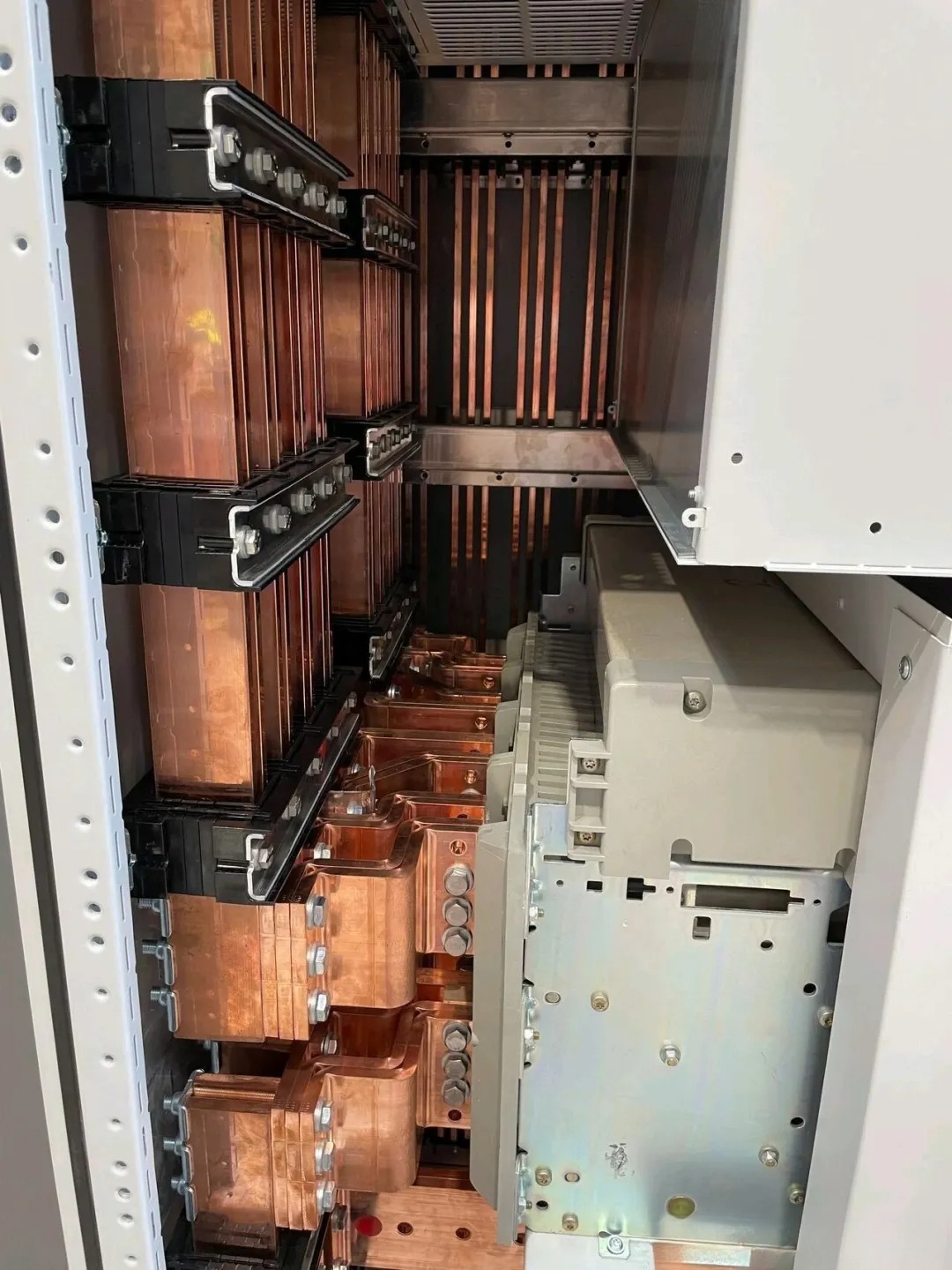
Use horizontal busbars to guide heat away from breakers before transitioning to vertical runs
-
Apply parallel laminated busbars to reduce skin and proximity effects
-
-
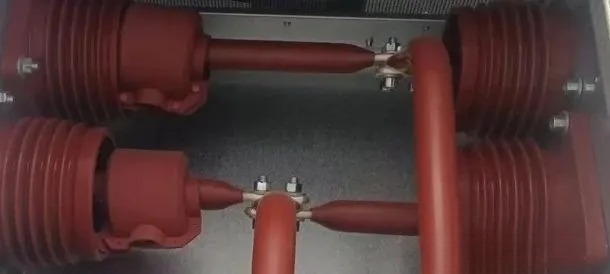
Utilize Tubular Busbars
-
AC current tends to concentrate near the conductor surface (skin effect), making tubular busbars more efficient at dissipating heat
-
A tubular busbar can also serve as a direct static contact terminal, reducing two connection points
-
Removing two joints (each with ~10μΩ resistance) in a 3150A circuit avoids nearly 100W of heat, which is significant in a contact box limited to 200W
Other Contributing Factors
Temperature rise is not only determined by structure and design but also by material quality and assembly techniques:
-
High-conductivity copper with low electrical resistance naturally produces less heat
-
Tightening torque of busbar bolts affects contact resistance
-
Higher torque = better pressure between connections = lower resistance
-
Proper tightening within rated bolt class significantly improves heat control
-
Real Results: Why Design Details Matter
In practical applications, these adjustments can be the difference between compliance and failure. For example:
“By switching to a tubular busbar and eliminating two contact points, we reduced over 99W of heat dissipation—nearly half of the acceptable limit inside a contact box.”
This shows how refined engineering, rather than overdesign or excessive materials, can effectively address thermal risks.
✅ Conclusion
Thermal management in switchgear is no longer just about busbar cross-section. A holistic view is needed—one that includes contact resistance, airflow design, skin effect, joint quality, and localized heating behavior. With Thermal Network Technology, engineers can identify and solve real overheating issues before they become failures.
At FATENG Electric, we continuously apply TNT principles and structural optimizations to ensure long-term operational safety and performance of our MV and LV switchgear.
CONTACT US
Email: ethan@fatengelectric.com
Whatsapp: +86 18051690281