The UL1558/IEEE C37.20.1 standard is the American standard for low-voltage power switchgear, designed for primary main distribution switchgear requiring high-performance parameters, system-level protection, and high reliability. The primary configuration must meet complex system application requirements, featuring modular designs for incoming, bus-tie, and outgoing circuits, enabling flexible cabinet assembly to accommodate various application scenarios while minimizing the number of switchgear units and maximizing economic efficiency.
A typical primary outgoing circuit configuration includes horizontal busbars arranged at three positions on the rear of the cabinet—upper, middle, and lower. This allows the horizontal busbars to be located at the top, center, or bottom of the rear section, providing great flexibility in design. The three sets of horizontal busbars can serve as backups for each other, operate independently, or run in parallel. Each busbar set supports up to 6000A current with a short-circuit capacity of 150kA, and a single busbar can carry the full load. High-current incoming and outgoing lines and bus-tie connections use frame-type circuit breakers exceeding 3200A, installed within a single switchgear unit, which can accommodate two 3200A frame breakers arranged in two layers.
As shown in the figure below, two sets of incoming and outgoing lines may connect directly to the middle horizontal busbar at the rear of the cabinet; alternatively, incoming lines may go to the upper section, while a 3200A frame breaker serves as a bus-tie between the middle and lower busbars. Alternatively, two-tiered 3200/4000A frame breakers can both act as bus-tie breakers connecting the upper-middle and middle-lower busbars.
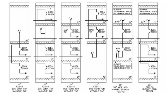
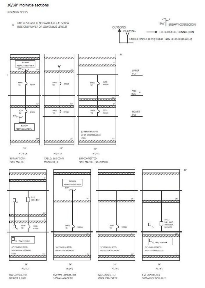 Similarly, for 4000/5000A single-layer incoming and bus-tie breakers, they can directly connect to the upper or lower rear busbars or link via busbars. Additionally, withdrawable fuse units can be installed for front maintenance. For frame breakers rated 2000A and below, four units can be installed in one switchgear cabinet, which is standardized with four compartments from top to bottom. This four-tier breaker arrangement offers greater flexibility and can also function as a bus duct bridge. The single-line diagram illustrates only a portion of possible configurations. The three busbars can be connected to frame breaker outputs, interlinked via bus-tie breakers, or used for incoming feeders, direct output, etc.
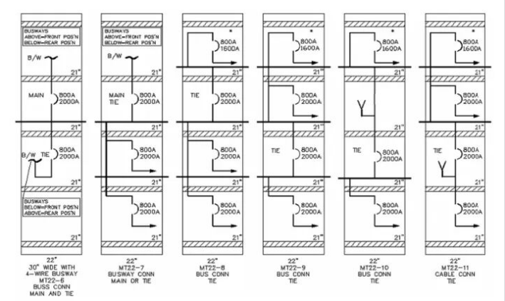 There are numerous possible combinations, allowing highly flexible primary configurations that minimize the number of switchgear cabinets required.
 According to the C37.20.1 standard, derating factors for two, three, and four withdrawable frame breakers are specified. For four frame breakers, the allowable current ratings are reduced by 50%, 60%, 75%, and 90% respectively. For example, if four 2000A frame breakers are installed, their permitted operating currents would be 1000A, 1200A, 1500A, and 1800A respectively, resulting in a total current capacity of 1000 + 1200 + 1500 + 1800 = 5500A.
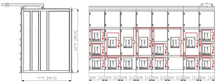 Connecting cables for four frame breakers require substantial space. A UL1558 low-voltage switchgear cabinet housing four 2000A breakers has a width of 22 inches (22 × 25.4 = 558.8 mm), depth of 70 inches (70 × 25.4 = 1778 mm), and height of 90 inches (90 × 25.4 = 2286 mm). Each frame breaker requires its own dedicated compartment for cable connections, typically needing 25 inches (25 × 25.4 = 635 mm) of depth. For 2000A breakers, six 500MCM copper conductors are used, requiring a minimum bending radius of 330 mm; alternatively, five 750MCM copper conductors require a minimum bending radius of 534 mm. Therefore, the cabinet base or top plate must provide space for 4×4×6=96 cable entry/exit holes—equivalent to installing 96 M40 gland plates. Using four-core cables reduces footprint area, but sufficient space remains necessary for proper cable bending and connection.
A typical primary outgoing circuit configuration includes horizontal busbars arranged at three positions on the rear of the cabinet—upper, middle, and lower. This allows the horizontal busbars to be located at the top, center, or bottom of the rear section, providing great flexibility in design. The three sets of horizontal busbars can serve as backups for each other, operate independently, or run in parallel. Each busbar set supports up to 6000A current with a short-circuit capacity of 150kA, and a single busbar can carry the full load. High-current incoming and outgoing lines and bus-tie connections use frame-type circuit breakers exceeding 3200A, installed within a single switchgear unit, which can accommodate two 3200A frame breakers arranged in two layers.
As shown in the figure below, two sets of incoming and outgoing lines may connect directly to the middle horizontal busbar at the rear of the cabinet; alternatively, incoming lines may go to the upper section, while a 3200A frame breaker serves as a bus-tie between the middle and lower busbars. Alternatively, two-tiered 3200/4000A frame breakers can both act as bus-tie breakers connecting the upper-middle and middle-lower busbars.